Latest Posts

Insights into Continuous Liquid Interface Production (CLIP) and Digital Light Processing (DLP) 3D Printers

3D printing technology is often used to construct highly complex objects of different kinds, properties and materials. Despite its numerous advantages, one major drawback of 3D printers is its traditionally slow speed. For instance a typical 3D printing machine such as Stereolithography (SLA) can take several hours to print a 55mm diameter object and maybe several days to complete a larger object. To overcome this major industry challenge, several 3D companies have come up with more updated and efficient technologies that guarantee quick speeds and utmost accuracy. The modern technologies include Continuous Liquid Interface Production (CLIP) and Digital Light Processing (DLP).

a) Digital Light Processing (DLP)

DLP is a type of stereolithography that is popular for performing rapid prototyping services. The technology uses projector light to perform photo-sensitive polymer cures instead of the traditional laser beam. Although DLP was first developed in 1987 by Larry Hornbeck of Texas Instrument, the first printed installation of 3D printed model with photopolymer technology was published in 1981 by Hideo Kodama of the Nagoya Municipal Industrial Research. DLP prototyping service is very expensive since it uses costly components such as photo-sensitive resin.

How Digital Light Processing Technology Works

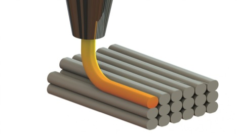
The Digital Light Processing printer works by projecting an image over the resin surface. The resin solidifies as the printer platform finalizes the release process. In a nutshell, a repeat process begins immediately after a new layer of resin is released, coated and cured using light. Once the 3D image is fully developed, the vat is dried out to expose the solid model. The other processes that may be necessitated in the finishing stages include chemical bath, UV curing and support material removal.

The time it takes to produce 3D objects using DLP typically depends on the size of the model under construction. On the other hand, the benefits of using DLP 3D are numerous, they include the ability to print and produce high resolution objects at high speed. Some of the applications that use this technology besides 3d printing machines include cell phones, movie projectors and standard projectors.

b) Continuous Liquid Interface Production (CLIP)

The Continuous Liquid Interface Production technology by Carbon 3D is a relatively new 3D technology that uses several thermoplastic engineering technologies to produce great finishes and resolution. The CLIP chemical process works by balancing oxygen and light to discriminately cure photo liquid resin. The technology is very popular in the field of medicine, consumer electronics and automobile.

Continuous Liquid Interface Production technology uses components such as UV curable resin, oxygen permeable window, dead zone, projector and a build platform. CLIP is highly efficient compared to other 3D printing processes because it allows the use of tunable photochemical procedure instead of the outdated mechanical procedures.

How the CLIP Process Works

The process is carried out by projecting UV images in continuous sequence. During the development stage, images are fed into the system using a digital light projector via an oxygen permeable UV transparent screen. This process takes place beneath a liquid resin bath. CLIP normally creates uncured resin between the object and window by controlling the oxygen flux. The thin layer of uncured resin is called the dead zone. Since a continuous sequence of UV images is reflected on the surface as the object being drawn, the technology makes it easy to continuously grow 3D objects without interruption.

The Advantages of Using CLIP Technology

The Carbon CLIP printer is highly efficient and fast; this advantage has made it possible for users to overcome many traditional 3D printing problems such as lack of speed. In addition, the 3D continuous printing process gives Carbon Clip the ability to develop parts without visible layers. The other CLIP advantage lies in the technology’s ability to eliminate weaknesses between the printed layers.

For this reason, users can also use the technology to develop end-user components and prototypes with nearly no visible layers while ensuring perfect finish. Carbon materials can be used to construct production components and prototypes needed by engineers and designers. Some of the most preferred materials include glass filled nylon, which is temperature resistance and the highly resilient injection molded polyurethane elastomer.

Extrusion deposition: Fused Deposition Modeling (FDM)

Fused Deposition Modeling stands out as one of the most commonly used additive fabrication techniques. A 3D company called Stratasys uses FDM as trademark as such various open source community entities and vendors to use the term thermoplastic extrusion when talking about the same technology. Printers that use FDM technology are designed to create 3D objects, one layer at a time, beginning with the bottom part.

Foto by Markelapellaniz

How Fused Deposition Modeling System Works

The development process technique involves heating and thermoplastic filament extrusion. During the pre-processing period, 3D CAD file provides an accurate path that helps facilitate thermoplastic extrusion. When the production process kicks in, the thermoplastic is heated and transformed into a liquid state by the 3D printer. The material is then deposited along the extrusion bath in the form of fine beads. The production process also involves buffering and removal of 3D scaffolding material. The final FDM post-processing process involves breaking off the support material.

Some of the key components in a typical FDM machine include thermal housing, extrusion nozzle, plastic filament supply coil and the X-Y-Z stage system. FDM operates following the X-Y-Z axes by drawing a layer of the model, one at a time. When undertaking thermoplastic extrusion, a plastic filament is removed from the coil in order to facilitate the movement of materials to the extrusion nozzle. When the nozzle reaches over the table surface, it releases several layers of plastic material. The nozzle features a device designed to control melted plastic.

Once the plastic material cools, it hardens almost immediately. The support columns are then removed and the surface finalized. Fused Deposition Modeling is a relatively quick and less noisy technique, especially when working with small components. FDM also offers greater strength and is applicable to a lot more materials compared to other competing dimensional printing technologies. Laser Sintering technology works in a similar manner as FDM when it comes to the production of low-volume, functional plastic prototypes, but FDM equipments are much more expensive.

FDM Printers Classification and Analysis

FDM 3D printers in the market are classified based on various factors, including design series, production series and idea series. The production series printers are developed to bring out agility and aesthetics at every developmental stage thanks to ability to use different material properties and colors for tooling and prototyping. The idea series concerns, issues such as printer model and prototype cost and level of user friendliness. Lastly, design series FDM printers are developed to make designs, durable and dimensionally stable.

Positives and Negatives of Using Fused Deposition Modeling (FDM) Technology

FDM has become popular because of a number of reasons, including low noise levels, reliability, high accuracy, professional finishes and office-friendliness. The technique can also be used to produce a wide range of materials. For instance, the production grade thermoplastics produced using FDM are usually environmentally friendly and mechanically stable. The major downsides of FDM technology include slow speeds on certain geometrical compositions and poor layering adhesion. FDM technique also requires expert knowledge.

Laser Powder Forming (LPF) and Laminated Object Manufacturing (LOM) 3D Additive technologies

a) Laminated Object Manufacturing (LOM)

LOM is a highly integrated additive technology that can be used to produce accurate finishes, even though the stability of paper objects falls short of those manufactured using most RP techniques. The objects developed using LOM look very similar to wood. LOM technique can also be deployed on a vast range of materials, besides paper such as ceramics, metals, plastics and composites, but on a limited scope. A typical Laminated Object Manufacturing machines feature components such as portable mirror, heater roller, wastepaper take-up roller, paper feed roll and laser.

The other critical operating apparatus includes smokestack and sealed chamber. Over the years, variations of LOM have also been developed by companies such as Mcor Technologies Ltd of Ireland, Helisys, Cubic Technologies and Solido 3D of Israel. The Mcor technology uses a knife in place of laser to cut and separate various 3D layers, before applying a bonding adhesive. The success of Mcor product is attributed to its low cost and excellent marketing strategies. Helisys, which was once a leading supplier of LOM in the US ceased operation in 2000, but its products, are still marketed by Cubic Technologies.

The Pros and Cons of Laminated Object Manufacturing Technique

Materials used in LOM object development, such as copier papers are generally very cheap. However, this technology is yet to be fully adopted as a mainstream additive technique. Some of the popular LOM application areas include the biomedical field and the process of making fluidic components and instrumentations. On the downside, the copier used in LOM is cheap and unstable because the material absorbs moisture fast. The end product can also appear warped and inaccurate. The other negative point includes LOM’s limited ability to create detailed 3D objects.

b) Laser Powder Forming (LPF)

Under the Laser Powder Forming technology, a computer controlled system is used to trace the object shape. In recent years, this laser fusing technology has gained wide acceptance among industry players because it allows users to fabricate dense objects as well as metal components at quicker speeds.

How Laser Powder Forming Technology Works

The laser released by LPF is focused using a powerful lens that is controlled by the movable joint. During the development stage, the X-Y-Z fabricates every layer of the object under development. The laser beam delivery process is fairly flexible and can be undertaken either using fiber optics or a simple right angle mirrors. The metal powder is normally fed into the system and distributed around the head using inert pressurized carrier gas or gravity. The inert gas helps cover the melt pool better layer surface wetting and adhesion.

The object created by this technology is usually placed on a rotating build platform to make it easy fabricate on multiple angles. Some of the popular metallic materials that are often used during Laser Powder Forming include copper, titanium, stainless steel and aluminum. These materials can be fed into the system in the form of wire or powdered feedstock. When it comes to laser, the power can range from a few 100 Watts to 20KW and higher. The amount of wattage used generally depends on feed rate as well as the type of material being used.

The LPF process may require finish machining to create more desirable objects. However, unlike laser sintering Laser Powder Forming does not require secondary firing process. LPF technology is mostly used in fabricating molding tools. The technology can also be used on a wide industrial scale to fabricate titanium metal components in the aerospace industry. Several studies about LPF have been initiated by various governments and university laboratories in the US, Asia and Europe to expound on the full potential of this additive technology.

Advantages and Disadvantages of Laser Powder Forming

Laser Powder Forming technologies offers several advantages over similar technologies. The benefits include the ability to develop large tools and components in a shorter timeframe using various metal alloys and composite materials. Some of the disadvantages of using LPF machinery include its huge size, high energy consumption, high operating cost and limited geometric freedom. The undercuts produced by LPF during the 3D development process may also require secondary machining.

Inkjet, Polyjet and Multijet Technologies

a) 3D inkjet printing technologies

There are several types of 3D inkjet printing technologies in use today; they include thermal phase change inkjets or ballistic particle manufacturing (BPM) and Photopolymer Phase Change Inkjets. Inkjet technologies use squirting to convert build material into a melted or liquid state. The object often hardens after it is released to form a solid mass. Solidscape is one of the pioneer companies when it in inkjet technology, thanks to its reputation for producing fine finished products. This technology is often used to develop complex medical implants and jewelry.

How Solidscape Inkjet Technology Works

Most Solidscape machines use wax support materials and plastic object. These materials are often used while in a molten liquid state. During the material processing, thermal insulated tubing is used to transfer the liquid into the jetting head. The head releases minute drops of the liquid material following a predetermined geometry in order to create different object layers. Once the layer of the object is fully developed, the milling head pushes over the layer to create a uniform flat thickness.

When the layers are being straightened, the vacuum uses a special filter to capture all the left over particles. During the next phase of development, the elevator table moves down to capture the upcoming layer one at a time. This process can only take place after fabrication, when the nozzle is clear of any clogs. When a clog appears, the jetting head must be cleaned before the process is repeated. Once the object is developed, the wax supporting material can be dissolved or melted for reuse.

The Positive and Negatives of Thermal Phase Change Inkjets

The Solidscape technology is very popular because it produces refined objects with finest details. On the downside, the technology can be painfully slow because most operations require object casting because the technology is often used to develop transient rather than fully functional components.

b) Photopolymer Phase Change Inkjet Technologies

Although Polyjet technology is a photopolymer based technology, it uses the layer-wise deposit to create objects and support materials using an inkjet head. This powerful 3D technique can be used to produce very accurate and smooth components and prototypes. The technology can also be devised to produce complex geometries and walls using a wide selection of materials. This technology was unveiled sometime in 2002 by an Israeli based firm called Object Ltd.

3D Polyjet Systems

Some of the most powerful photopolymer systems in use today include InVision by 3D systems and Object’s Eden and Connex500. The office-friendly Eden series machines can produce thin layers of up to 16 microns. The Connex500 system unveiled in 2007 was the first machine of its kind to operate simultaneously using two fabrication materials. This capability has made it easy for the system to produce parts with different properties and volume.

Positives and Negatives of Using Phase Change Inkjets

The end objects produced by Polyjet technology often exude excellent accuracy and fine resolution. This office-friendly technology also allows the use of different materials, including digitally combined materials. The negatives of using this technology include high machine purchasing cost. The components produced using Polyjet technology must also undergo various secondary processes to eliminate messier support systems.

c) Multijet Printing Technology

This rapid prototyping printing process is offers a quicker turnaround, especially when it comes to smooth finishes, high resolution and complex geometries. This additive technology can also be used to print thin layers of wax support materials and UV curable liquid plastics. One of the key components in Multijet Printing machine besides the photopolymer materials is the UV bulbs.

Binding of Granular Materials and Techniques

3D printing has greatly revolutionized the printing process since its introduction in the late 70’s. The technology has made it possible for 3D companies to create low cost prototypes and specialized components for various industrial and specialized needs. The granular binding process involves fusing different layers of granules in a repeat process in order to build a desired object. In most part, the sintering process that helps create solid media is often done using a laser beam and support systems.

On the other hand, although the vast majority of 3D printing is carried out using molten plastic; one branch of 3D printing that is growing fast is the one that involves metal fabrication and forging. Good examples of these additive metal manufacturing processes include Selective Laser Melting (SLM), Electron Beam Melting (EBM) and Direct Metal Laser Sintering (DMLS). Speaking in the same breadth, it is important to recognize that metal printing techniques are slightly different from plastic printing technologies.

a) Direct Metal Laser Sintering (DMLS)

DMLS is an efficient, additive making process with a huge leverage over other 3D printing techniques because of its versatility. Under this technique, you can work with various materials including special metal alloys, polymer-based materials and other different mediums. The technology was first developed by the Munich, Germany based firm, EOS.

How the Direct Metal Laser Sintering Technology Works

The DMLS process involves applying thin sheaths of metal powder on the surface earmarked for printing. The laser is then used to sinter the powder in order to ensure slow but steady fusion when constructing 3D objects with thin layers. Since this technology is able to read and follow intricate geometries assigned by the CAD file, layers with a thickness as small as 20 micrometers can be fused easily layer-by-layer. Once the printing process is complete, the object is left to cool. DMLS end products are usually removed from the residual tresses; as such, it is easy to work with metals and other conducive materials under pressure.

b) Electron Beam Melting (EBM)

Electron Beam Melting is an addictive manufacturing process that works the same way as Selective Laser Melting (SLM) to produce detailed and highly dense models. However, EBM uses an electronic beam instead of laser to melt the metal powder medium. This technique is often applied to a limited number of metals used in the aerospace industry such as Titanium alloy and cobalt chrome. The biggest advantage of using EBM technology compared to metal sintering techniques is its ability to produce sturdy, dense and void-free components because it operates above the melting point.

c) Selective Laser Sintering (SLS)

SLS is an addictive laser manufacturing process that involves sintering powdered materials to develop 3D objects. The technology uses a high-powered laser to fuse materials such as glass, plastic and metal powders to create mass objects. However, this technology is much more suitable for producing small components and rapid prototyping. Today, laser sintering is used in direct fabrication of ceramic objects and metals.

Laser sintering is eerily similar to stereolithography, only that a laser beam is passed over the surface of a compacted powder. To attain the desired layer thickness, the powder is spread using counter rotating roller and a piston. Under laser sintering and stereolithography, the motors used to develop 3D objects are guided by CAD data input. The SLS technology was first produced and patented in the 80’s by Dr. Joe Beaman and Dr. Carl Deckard while a company called 3D Systems uses the term Selective Laser Sintering (SLS) as its trademark.

Advantages and Disadvantages of Laser Sintering Technology

Since laser sintering is often used to produce a wide range of engineering plastics and metallic components. The technology has the same advantages as those offered by less expensive additive technologies. Some of the products that can be made using this additive process include medical and aerospace products. The downside of using laser sintering technology includes its complex nature and limited application. The technology is also expensive because it uses components such as scanners and laser to run efficiently.

Possibilities of 3D Printing

News today portray additive technology as being far from having a complete evolution. On the contrary, most are actually quite mature.

The thermoplastic extrusions at the moment have well over eleven thousand patents and applications for the patents in the United States; probably more in other countries largely involved in this sector. Books and academic papers on the same are also been published.

Read More

What are the Steps Involved in Making Something – i.e. the Process Chain?

i. Conceptualization and Creation of a CAD File

Designing of the 3D object is the first step in 3D printing which can be done by drawing the object or downloading the various files that can be sourced from the internet.

A wide range of computer-aided design file types are available, and they come in a variety of parameters, formats, and names.

A detailed description of the object to be built by the 3D printer is required for the printer to operate. The description of the object to be created then needs to be placed in the CAD file to get the three-dimensional description of the object.

Operating the 3D program can be a daunting task for someone who has not been familiar with the program, but there are a lot of helpful guides for different programs. One may need to spend some time to familiarize themselves with the computer-aided design file.

Other individuals may opt to create models using the Google SketchUp application. Tools are available with which one can draw lines and shapes. The SketchUp program is easy to learn program for beginners. Other open-source programs available include the high-power Blender program and the less robust program 3D Tin.

ii. Converting the File to a Standard Tessellation Language

Most additive manufacturing systems use STL files as the standard file. An STL file is simply a triangulated representation of a 3D CAD model.

As a result, faceting of the 3D model will take place. STL files can be automatically generated from CAD programs except the SketchUp program that may require a plug-in. The STL files have been used for a long time, and they were the first machines to be available commercially.

When exporting programs to STL, parameters such as the angle tolerance, chord height, deviation, and poly count affect the faceting of the STL.

The printed physical model will resemble the STL file. If the STL file appears coarse and faceted, then that is how the 3D physical model will also appear.

Errors may also arise during the transfer process. Some mistakes may end up compromising the printing capability of the machine. Software tools are available with which the STL tools can be inspected and repaired in case of any errors.

iii. Transferring the STL File to the 3D Printer and Setting of the Parameters

After generating the STL file, it should be exported to the software that will run the three-dimensional machine. The process of transferring the STL program involves two steps.

The first phase includes the modification of the STL program within the printer. The second step commands the machine by the use of G-codes depending on the specifications required.

Standard open-source programs utilized in this process include ReplicatorG used in positioning of motors and the Skeinforge that is used in setting parameters like the extrusion temperature.

The process may take between twenty minutes to an hour or more depending on the size of the object and the resolutions being used.

After completion of the transfer process, the file is sent to the printer. The transfer process can be done using a USB cable which is used to connect the computer to the printer.

Other manufacturers prefer copying the file to an SD card which is then inserted into the printer. The use of the SD card allows the printer function independently without having to coordinate with the computer.

iv. Printing and Removal of the 3D Object

The use of the SD card saves time spent in the printing process unlike the utilization of a USB cable. The process of removing the object from the printing machine may involve a lot of work to separate the object from the surface upon which it was formed.

v. Cleaning of the Surfaces and the Object

The surfaces upon which the object was built may require cleaning by use of solvents or light. The support structures may also need to be removed. The removal of these structures may require cutting or dissolving in cases where soluble materials were used.

3D Printers Development and Patent Issues

Open-source 3D printers have demonstrated their ability to replicate the existing technology. Their performance level at the moment can work well for business applications that are less essential, and for hobbyists.

The most important reason for building a machine apart from just keeping it going, is to use it in making other things. If the 3D printed objects are not attractive or useful, then the chances of them being taken up by the hobbyist are considerably slim.

The people interested in machines that make things, often aim at developing a revolutionary application that will have the technology gain wide acceptance. One can get a machine already fully assembled, and then embark on improving the accuracy, and make the machine much easier to use.

OS Hardware Movement vs. OS Software Movement

Software and hardware are two very different and independent sectors. Being able to give functionalities and abilities to a machine using software development is pretty much the same as being able to learn a foreign language.

As for designing of hardware, it is like being a physician. It requires not only the knowledge to assemble parts but also the necessary experience and expertise. The basics can be done by anyone, but to tackle the electromechanical systems requires more of the knowledge and experimentation to have desirable results. After all, the basics already exist. Progress in the quality of results is what makes a 3D printer machine more desirable.

A deeper understanding of the interaction between the machinery and the materials is needed in the hardware movement; something that poses challenges even to the experienced engineers.

Software iterations can quickly be done since one only requires a computer and the programming knowledge. The applications of the results are also much easier and more direct.

As for hardware iteration, it must be carried out practically and requires measuring, laboratory space, and instrumentation. This can take minutes or even days to produce a complete and efficiently-functioning machine. The hardware part requires much more commitment as compared to the software aspect.

Comparison of Open-source and Traditional Engineering Development

The difference can be derived from the drive; pretty much the same as comparing Socialism to Capitalism.

In the traditional electromechanical engineering development process, detailed and explicit design goals are written down first. After that, one particular approach is picked, its criteria of performance defined, and the budget determined. Schedules are set, materials for the design are acquired and after completion, the final product is tested to determine if the goals set in the design have been accomplished or not.

In this process, the goals might change along the course of the project altering the schedule and the budget. This process is not as perfect; the main aim is getting done with the job.

As for the Open Source, the environment is rather unstructured with less central authority, goals and schedules. People work on their 3D printer projects in the manner they best can. There is no defined professional consequences or goal-directed efforts. Since the work is for the good of all taking part in the project, and the software and hardware aspects of a project have undefined periods of time to complete, a sense of urgency becomes more difficult to establish.

The Patent Issues

The legal framework touching on the intellectual property is subject to change with the evolution of 3D printers’ technology. The economic forces behind intellectual property cannot be underestimated. The large companies can easily litigate small companies. It is their duty to do so, so as to protect the ongoing value and the property of its shareholders. This is quite unfair and is something that should worry the open-source community.

However, the giant companies do not just ignore the open source community. Violating a patent causes more injury to the company’s owners than violating copyrights. Everyone is quite proprietary about their owning. At the moment, the US additive fabrication field has over 11,000 patents and applications for the same. This indicates that as time progresses, it will get more difficult not to interfere with previous work, and therefore keenness should be observed to avoid patent violations.

Evading Legal Problems while Progressing

The progress of the open-source developers highly relies on their ability to come up with original inventions. The inventions should get to the patentability and free-licensing level. It is a much better and smoother journey for the open source developers when they act altruistically rather than falling into the temptation of only aiming at making profits.

Building upon already existing work is possible and allowed within some sections of the legal framework. But one may get to a situation where they cannot find methods and materials that will not violate the patent of the original creators. This ends up leading one to the patent violation, hence faces legal consequences. All the effort and time one had dedicated goes to waste.

It is, therefore, more logical to come up with new inventions rather than having to battle with the legal systems. One can always be sure that the patent holders are always looking.